Prototypes
"Practice makes perfect", and the road to perfection is littered with crumpled paper sketches, prototypes, failures and dead ends. In this section, we'll gather the work of Rasmus Sørnes that led up to his astronomical clocks.1. Mechanical escapement prototype
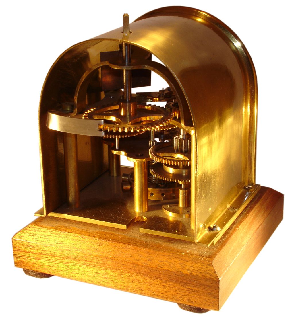
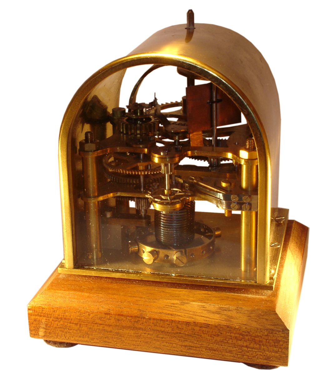
Seen here is a mechanical escapement prototype constructed by Rasmus Sørnes to prove the concept of his constant power escapement. He seems to have been happy with the function, as he also built a beautiful housing for it, out of brass, glass and oak.
2. Unfinished clock with electrical escapement
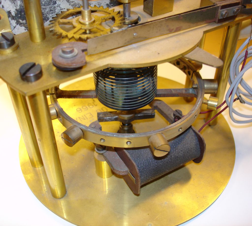
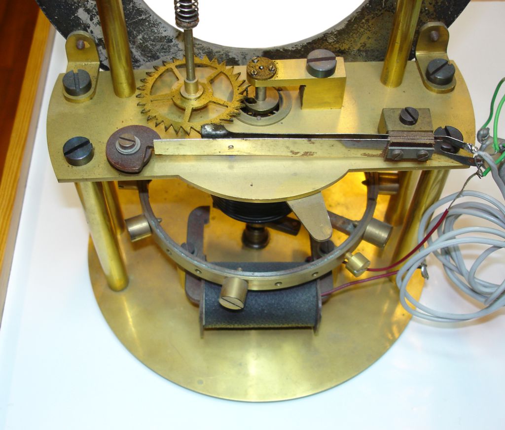
This is not an astronomical clock, but a small mantelpiece clock with Sørnes' own electrical escapement. According to the engraving (KAREN OG EINAR JUL 1966 R. SØRNES), this clock was prepared as a gift, but for some reason not finished. Could be something went wrong, and he started over again.
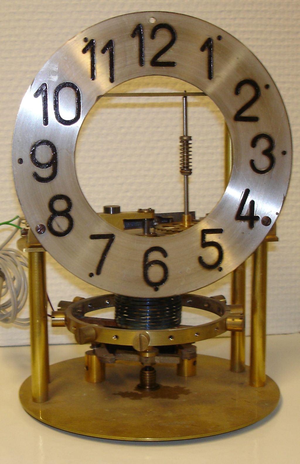
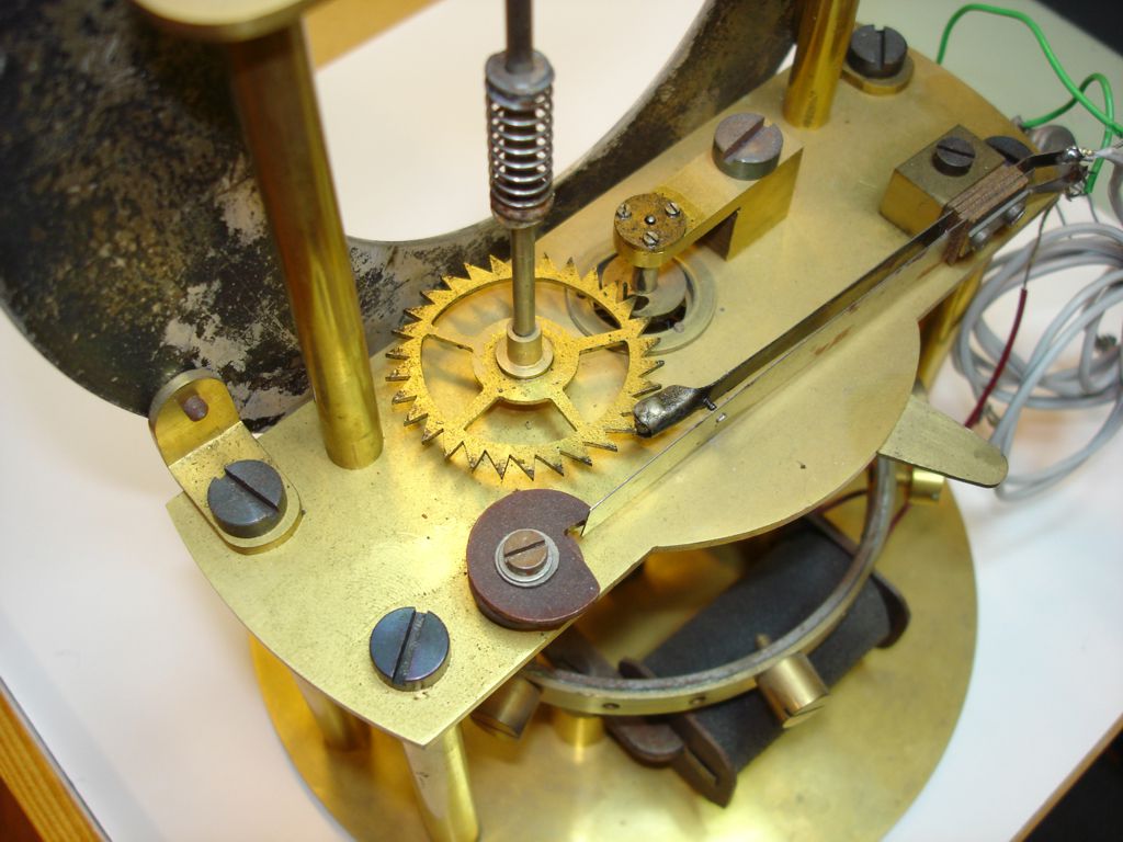
As only the framwork and the electrical escapement is in place, this gives us an excellent opportunity to study the principles of the escapement. See pictures and video content below for more details (click to enlarge).
Escapement operation
-
Seen under the dial is a spring loaded balance wheel, which is the equivalent to a pendulum. The wheel's moment of inertia, and the spring constant, are chosen so that the wheel performs one oscillation per second.
-
The major source of inaccuracy comes from temperature changes, which causes both the wheel size and spring constant to change. Most of the resulting error can be derived from the spring constant, and the solution is to make the wheel change in a way that cancel out the change of the spring constant. Details about this can be found here.
-
Kinetic energy is lost in bearings, due to air friction, and by moving the hands, and must be added continously, or the balance wheel soon would stop. This is accomplished by the electromagnet seen under the balance wheel.
-
A permanent magnet is attached to the axis of the balance wheel, and rotates in the gap of the electromagnet. Every second, when the balance wheel is approaching its neutral position, an electrical switch is closed for a short time. This magnetizes the electromagnet, which repells the permanent magnet, thus giving the balance wheel the impulse needed to keep it running.
Source reference
- All images and video content in this article are copyright Andreas Nilsson